
How To Wire A 4 Pin Relay Switch Diagram Wiring Diagram
The wiring diagram for a 5-pin relay typically includes all of the same components as a 4-pin relay, plus an additional power source for the control circuit. When wiring a relay, it's important to use proper gauge wire and ensure correct polarity to avoid damage to the relay or other components.

Other Car Parts Vehicle Parts & Accessories BRAND NEW UNIVERSAL 24 VOLT
Wiring 4 Pin Relay: A Comprehensive Guide. A 4-pin relay is a commonly used electrical component that allows you to control a high-current circuit using a low-current signal. It is widely used in automotive applications such as controlling lights, horns, and motors. Understanding how to properly wire a 4-pin relay is essential for anyone.
44 Luxury 12v 40a Relay Wiring Diagram
Quick and easy way to wire a relay to safely power added lights. Why you need a relay is also covered. This video will explain details of how to wire a relay.

Automotive 5 Pin Relay Diagram
A relay switch or a 5-pin is like a 4-pin relay, with the addition of pin number 87a. A 5-pin relay is wired the same as a 4-pin relay. The difference is that when a current isn't sent through pins 85 and 86, rather than breaking a single circuit, the 5-pin relay will switch to the circuit connected to pin 87a. How to Wire an 8-Pin Relay

Best Relay Wiring Diagram 5 Pin Wiring Diagram Bosch 5 Pin Relay
In this video I show you how to wire a 12 volt automotive Bosch style relay. This video covers both 4 and 5 pin 12VDC relays.Best Connections - 12voltwire.co.

12v 30a Relay 4 Pin Wiring Diagram Wiring Digital and Schematic
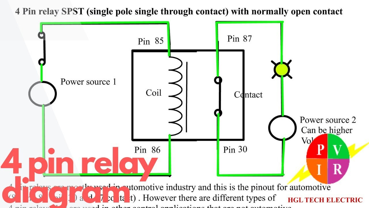
Normally Open (NO) 4-Pin Relay. Both these relays are very similar except that the 4-Pin relay doesn't have the '87a' or the Normally Closed (NC) pin whereas the 5-Pin relay has it. of automotive relays is the positioning of COM pin in the relay. Depending on position of the COM relays are further classified into: Type A Relay.
Remote Relay Wiring Diagram
Relays and wiring can be a real pain, and the whole process of testing and diagnosing can be daunting. If you simplify it and break it into pieces, it's not.

5 Pin 12 Volt Relay Wiring / 5 Relay With Socket Wire Harness Spdt 12
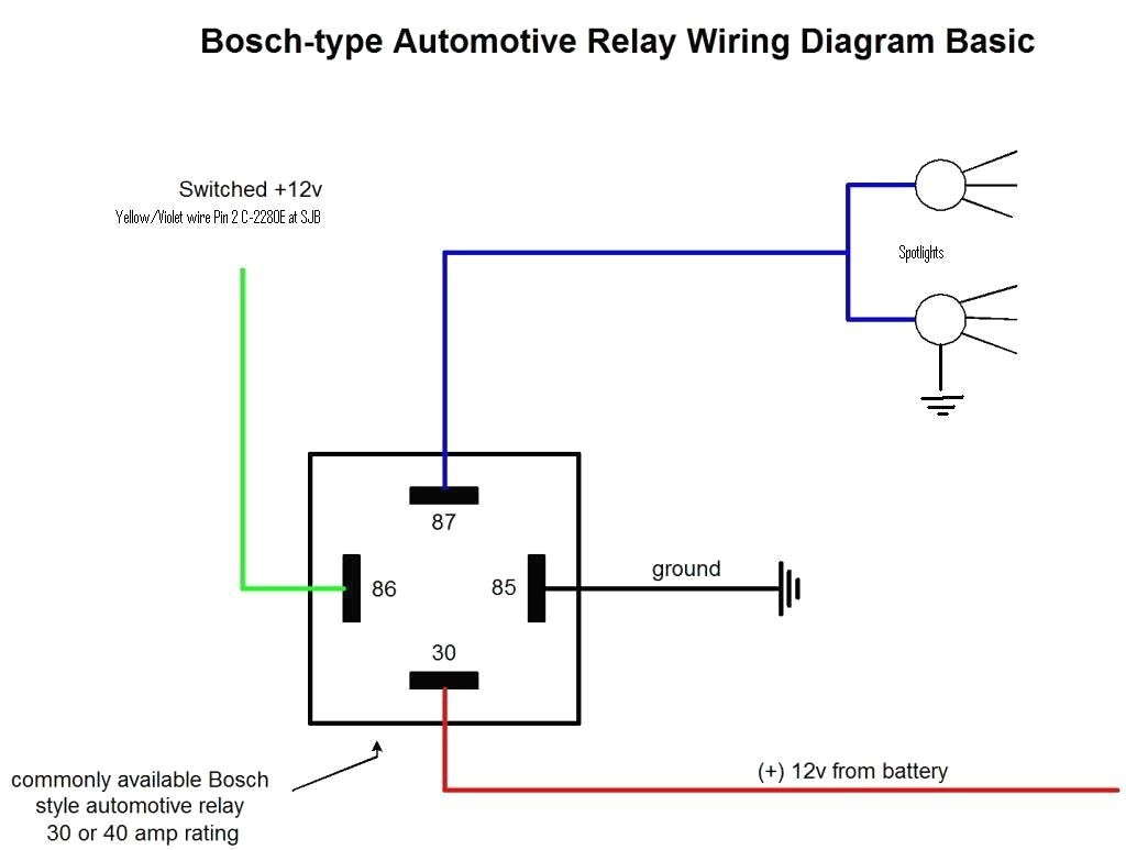
Four-pin relays are commonly used in the application of fog lights, LED lights, and automotive electronics. Wiring a four-pin relay is a simple three-step process: Connect a 12V battery to Pin 30 of the relay via fuse. Connect Pin 85 to the ground.
4 Pin Wiring Diagram Cadician's Blog
how to wire a 4 pin relay.Equipment used in the filming is Gopro Hero 8 fromhttp://Gopro.comOthe equipment used for filming is the iSteady gimble fromhttp://.

5 Pin Relay Wiring Diagram Use Of Relay
By definition, a relay is an electricity-operated switch. It is used in electronic circuits to regulate and control multiple operations. With the help of a relay, you can control a high current circuit via the setup of a low current circuit. Four-pin relays are commonly used in the application of fo.

5 Pin Relay Explained / 3 Wire Relay / Undo those taped connections and
Choose From a Wide Range Of Automotive Supplies. Shop At Amazon Online. Get Deals and Low Prices On relay 4 pin On Amazon

China 4 Pin Relay Wiring Manufacturers and Suppliers Factory
5-Pin-Relay-Wiring-Diagram-On-Relay-Case. According to DIN 72552 Standard, each pin of a relay is numbered 85, 86, 30, 87, and 87a. You need to know that a relay has two circuits, a coil circuit (also called a "low current circuit", or "inductive circuit"), and a high-amperage circuit. In a relay 85 and 86 pins are considered coil.

how to wire a 4 pin relay switch diagram Wiring Boards
No matter what you love, you'll find it here. Search 4 Pin Relay and more. Looking for Great Deals on 4 Pin Relay? From everything to the very thing. All on eBay.

4 Pin Relay Connection Diagram Smart Thermostat Wiring
Step 3: Connect the power source. The first pins to connect are 85 and 86, which are the coil pins. Connect one end of a wire to the positive terminal of your power source and connect the other end to pin 85 of the relay. Next, connect a wire from the negative terminal of your power source to pin 86 of the relay.
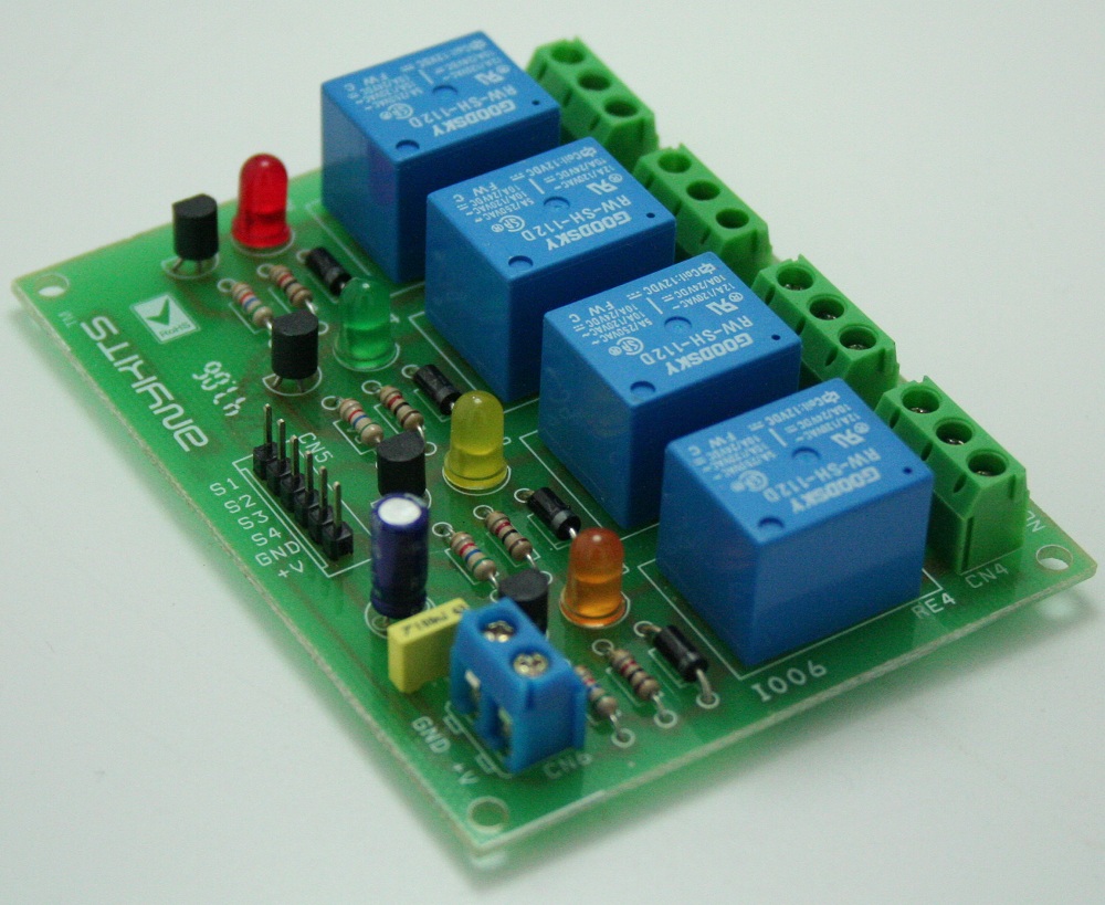
4 Channel Relay Board ElectronicsLab
A 4 pin relay is a commonly used type of relay, with four pins for easy wiring and installation. To properly wire a 4 pin relay with a switch, you will need to connect the following pins: Pin 30: This is the common pin, which is usually connected to the power source. Pin 87: This is the normally open (NO) pin, which is connected to the load.

4 Pin Relay Wiring Diagram Autok Dpdt Double Pole Double Throw Relay
Control relay wiring diagram example. Consider a 4-pin relay system that allows the dash-mounted light switch (Figure 7 labeled A) to control a high-current load, such as a headlight or fog light (Figure 7 labeled D). The relay acts as an amplifier, allowing a small current from the light switch to control a much larger current to the load..